
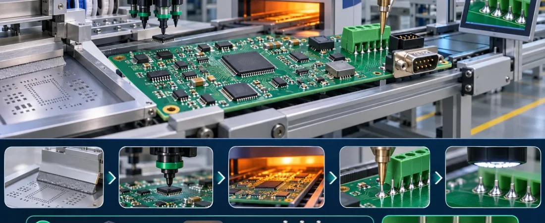
Mixed-technology PCBAs combine the placement density of surface mount with the mechanical strength, current capacity or connector options of through-hole parts. The challenge is not simply to run both processes. Each soldering and handling step changes what remains accessible, how much heat components receive and which defects become likely.
A robust route is selected from component restrictions, board geometry, side count, solder alloy, volume and inspection strategy. The same BOM may need a different sequence when connector height, bottom-side SMT or selective-solder clearance changes.
1. Map the available assembly routes
A common route is first-side SMT reflow, second-side SMT reflow, THT insertion and then selective or wave soldering. Alternatives include pin-in-paste, hand soldering for exceptional parts, or a dedicated pallet process. The cheapest-looking sequence is not necessarily lowest risk when it adds masking, rework or extra thermal cycles.
2. Protect components from repeated thermal exposure
Check package peak temperature, time above liquidus, moisture-sensitivity handling and any restriction on wave contact or bottom-side heating. Large connectors and thermal masses also change the profile. Record every planned heat cycle, including rework.
3. Select the THT soldering method from geometry
Wave soldering can be efficient at volume but requires compatible bottom-side clearances and orientation. Selective soldering limits the heated area but needs nozzle access and keepouts. Pin-in-paste can remove a separate soldering step, provided paste volume, lead protrusion and component reflow capability are validated.
| Route | Best fit | Main control |
|---|---|---|
| Wave solder | High-volume compatible bottom side | Pallet/mask, orientation, shadowing and thermal profile. |
| Selective solder | Mixed geometry and localized joints | Nozzle access, keepout, preheat and dwell. |
| Pin-in-paste | Reflow-capable THT with manageable paste demand | Stencil aperture, paste volume, lead protrusion and void escape. |
| Hand solder | Low-volume exceptions or repair | Operator qualification, tip temperature, dwell and evidence. |
4. Design footprints and panels for the route
Hole-to-lead relationship, annular ring, solder-mask openings, component stand-off and lead length affect fill and bridging. Panel rails must support the board through each machine; tall parts, clamps and pallets need clearance.
5. Build inspection and traceability into the traveler
Define which joints are checked after reflow and after THT soldering. AOI may lose line of sight once connectors are inserted; X-ray or visual criteria may be needed. Record program, profile, alloy, flux, machine and repair history.
6. Release complete assembly data
Provide BOM, centroid, drawings, polarity, component heights, approved alternates, THT lead dimensions and thermal restrictions. JEXPCB can coordinate DFM and process planning; the final sequence should be approved against actual equipment and product class.
Release checklist
| Input | Confirm before order | Evidence |
|---|---|---|
| Revision | Files, drawing and BOM use the same revision. | Controlled package or checksum. |
| Technical assumptions | Material, stack-up, process and acceptance criteria are explicit. | Reviewed quotation / DFM record. |
| Traceability | Required lot, process and inspection records are defined. | Traveler, report or certificate. |
| Change control | Deviation and substitution need named approval. | Written approval before production. |
Frequently asked questions
Can all THT parts go through reflow?
No. Confirm package, plastic and supplier temperature limits.
Is selective soldering always safer than wave?
No. It reduces exposure but still needs access, preheat and a validated window.
Technical references
- IPC — J-STD-001 and IPC-A-610 companion documents
- Global Electronics Association — IPC standards
- Indium Corporation — Mixed technology assembly resources
References checked 5 November 2026. Final process limits must follow component data, customer requirements and the selected assembly line.