
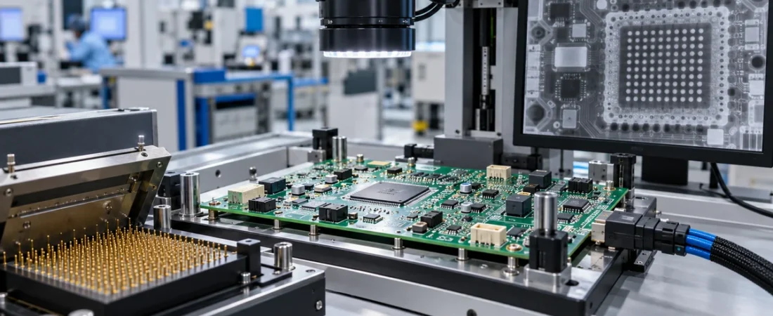
AI-generated editorial illustration of complementary PCBA inspection and test methods.
A PCB assembly can pass optical inspection and still fail at power-up. Another board can pass a short functional check while a hidden BGA joint remains marginal. These outcomes are not contradictory: AOI, X-ray inspection, in-circuit testing (ICT) and functional testing examine different evidence.
The practical question is therefore not “Which test is best?” but “Which failure modes must this build detect, and what combination gives useful coverage at the planned volume?” The answer affects layout, fixtures, programming, cycle time, quotation and production release.
Four methods, four different views of the assembly
| Method | What it is strongest at | What it does not prove | Typical preparation |
|---|---|---|---|
| AOI | Visible placement, polarity, solder and component-presence defects | Hidden joints or electrical operation | Inspection program, component library and acceptance criteria |
| X-ray / AXI | Hidden solder joints, BGA alignment, bridges and voiding indications | Firmware, full circuit behavior or every visible surface defect | Regions of interest, image criteria and trained interpretation |
| ICT | Electrical manufacturing faults at accessible nodes: shorts, opens and many component-value or orientation errors | Complete end-use performance | Test points, fixture or probe program, limits and diagnostics |
| Functional test | Specified board or product functions under powered conditions | Untested functions, latent defects or necessarily the root cause of a failure | Test specification, firmware, interfaces, loads, limits and fixtures |
AOI: fast evidence from visible surfaces
Automated optical inspection uses cameras and controlled lighting to evaluate what can be seen. A well-tuned program can detect missing or shifted parts, polarity and orientation errors, solder bridges, insufficient or excessive visible solder, and other geometry-related anomalies. It is especially useful after paste printing or reflow because feedback can reach the process quickly.
Its boundary is physical: an optical system cannot see through a BGA, bottom-terminated component or shield can. It also cannot establish that a correctly oriented IC is electrically healthy or contains the intended firmware. Shadows, reflective joints, component variation and poor programming can create false calls, so first-board validation and controlled acceptance criteria matter.
X-ray inspection: evidence from hidden interconnections
X-ray inspection is valuable when solder joints are hidden or when internal geometry matters. Depending on the equipment and method, it can reveal BGA ball alignment, bridging, missing or irregular connections, voiding indications, through-hole fill and other internal features. Nikon’s electronics inspection material, for example, describes X-ray analysis of BGA joints, voids, cracks and misalignment.
An X-ray image is still an inspection result, not an electrical or functional test. Image quality, viewing angle, component overlap and the pass/fail rule determine what can be concluded. A board may have acceptable images but the wrong component value; conversely, an image anomaly may require engineering review rather than automatic rejection. Specify which packages or joints require inspection and what report or images must be retained.
ICT: structural electrical testing with strong diagnostics
In-circuit testing contacts accessible circuit nodes through a bed-of-nails fixture or other probing strategy. It can find shorts, opens, missing parts, incorrect resistor or capacitor values, polarity errors and some semiconductor faults. Because measurements are linked to nodes and components, ICT usually gives more direct repair information than a final system-level failure.
Coverage depends on design for test. Dense layouts, BGAs and high-speed routing often reduce physical probe access; fixtures also add non-recurring cost and lead time. For prototypes or frequently changing designs, flying-probe testing may avoid a dedicated fixture but normally trades throughput for flexibility. Boundary-scan can extend access to compatible digital devices and interconnections, but it must be planned in the design and test architecture.
Functional testing: does the specified behavior work?
Functional testing powers the board and stimulates selected inputs, interfaces or loads to confirm specified outputs. It may check current draw, rails, communications, sensors, relays, displays or an application-specific sequence. The test can be performed at board level or after further product integration.
A “functional test” is not a universal package. The buyer must define the operating mode, firmware version, input stimuli, loads, limits, duration, connector pinout, safety conditions and output record. A pass only covers the exercised functions and limits. Keysight notes that even a 100% functional-test pass does not by itself prove a product defect-free because the conclusion depends on testability and coverage. Functional testing is therefore strongest when upstream inspection and structural tests have already removed basic assembly faults.
How to combine the methods
| Build situation | Practical starting strategy | Main reason |
|---|---|---|
| Early prototype, design changing | Visual/AOI where available, targeted X-ray for hidden joints, flexible electrical or bench functional checks | Avoid committing to a costly fixture before the design stabilizes |
| Stable, higher-volume PCBA with test access | AOI plus ICT and a focused functional test; use X-ray where package or process risk warrants it | Fast structural diagnosis plus confirmation of required behavior |
| Dense board with BGAs and limited test pads | AOI, targeted X-ray, boundary-scan where designed in, and risk-based functional coverage | Hidden joints and poor physical access create different gaps |
| Reliability- or safety-critical product | A documented test plan derived from product risk, regulatory needs and design verification—not a generic checklist | Acceptance evidence must match the actual hazards and requirements |
No line in this table means that every named method is always required. Volume, board architecture, defect risk, traceability needs and the cost of an escape should drive the plan. Sampling versus 100% inspection must also be stated explicitly rather than assumed.
What to include in a quotation or test specification
- PCBA revision, BOM revision, Gerber/ODB++ data and placement data.
- Applicable workmanship and acceptance requirements, including the exact standard revision or customer specification.
- Packages or joints requiring targeted X-ray and the required report or image retention.
- Available test points, netlist and any design-for-test constraints.
- Functional-test procedure, firmware, programming file, connector definition, fixtures, loads and pass/fail limits.
- Required coverage, sample rate, serialization, data format and record-retention expectations.
- Golden board or known-good unit, calibration needs and who approves test changes.
These inputs let a manufacturer quote programming and fixture work separately from recurring test time. They also prevent “AOI included” or “functional test required” from becoming ambiguous line items.
Frequently asked questions
Can X-ray replace AOI?
Usually no. X-ray is valuable for hidden structures, while AOI is efficient for visible placement and solder features. They answer different questions.
Does ICT make functional testing unnecessary?
No. ICT is strong at structural manufacturing faults and diagnosis. Functional testing verifies selected powered behavior. Either can leave gaps that the other covers.
Is a bed-of-nails fixture sensible for prototypes?
It depends on design stability, volume and fault cost. A flexible probe or bench setup can be more economical early; a dedicated fixture becomes more attractive when throughput and repeatability justify the setup.
What should “test coverage” mean in a purchase order?
Define it in measurable terms: nets, components, functions, interfaces, limits, samples and retained results. A percentage without a coverage model can be misleading.
Define the test plan before production release
When requesting a PCBA quotation, share the failure modes you need to detect, the available design data and the evidence you need at shipment. JEXPCB can review the requested inspection and test scope; method availability, fixtures, coverage and reporting should be confirmed for the individual project.
Explore PCB assembly services · Prepare your PCBA quotation package · Request a quote
Technical references
- Keysight: How In-Circuit Tests Ensure PCBA Quality and Reliability
- Keysight: A Unified Approach to ICT and Functional Test Integration
- Keysight: Finding Fault—testability and coverage
- Nikon: PCB X-ray analysis capabilities
- IPC: Checklist for Producing Rigid Printed Board Assemblies
Technical references checked 27 October 2026.