
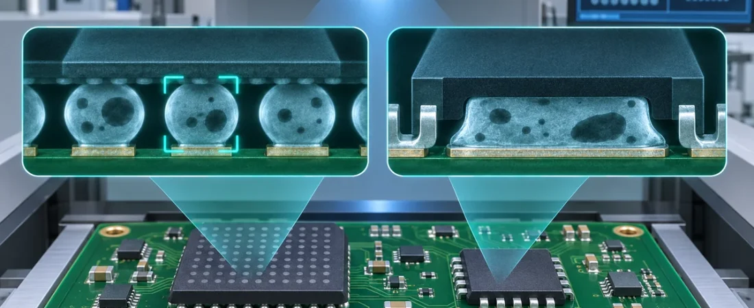

An X-ray image can show dark regions inside a BGA solder ball or a QFN exposed-pad joint, but the image is not a complete diagnosis. The same measured void percentage can represent very different risk depending on where the void sits, whether it is one large interfacial defect or many small internal pores, and what electrical, thermal and mechanical load the joint must carry.
The first mistake is to apply one percentage to every package. BGA balls, QFN perimeter leads and QFN/BTC centre thermal pads have different joint geometry and functions. Acceptance must be tied to the product specification, component data, customer requirements and the applicable revision of IPC or another agreed standard.
1. Separate BGA ball voids from QFN thermal-pad voids
For a BGA, X-ray primarily evaluates each hidden solder ball: shape, alignment, bridging, missing balls, head-in-pillow indications and internal density variations. Voids may be trapped inside the ball or concentrated close to the package or PCB interface. An interfacial void can be more concerning than an equal area dispersed through the middle of a well-formed joint.
For a QFN or another bottom-terminated component, the large exposed pad provides heat transfer, electrical grounding or current capacity, while the perimeter terminations provide signal and mechanical attachment. These regions need separate measurement algorithms. Combining them into one package-level percentage hides the condition that matters.
| Joint or region | What X-ray can indicate | What must be judged separately |
|---|---|---|
| BGA solder ball | Ball presence, diameter consistency, bridge, alignment and projected void area | Void position, interface involvement, head-in-pillow suspicion and package warpage evidence. |
| QFN perimeter lead | Solder presence and gross bridging, depending on resolution and angle | Wetting at the toe/heel, open joints and side termination quality may need visual or section evidence. |
| QFN exposed thermal pad | Total projected void area, largest void and distribution across the pad | Thermal/current path, package guidance, via pattern and whether voids interrupt critical heat flow. |
| Power BTC / D-Pak pad | Large-area density variations and solder coverage | Current density, thermal resistance and product-specific reliability requirement. |
2. Read the pattern, not only the percentage
Two-dimensional X-ray is a projected image. Features above and below the joint can overlap, and software threshold settings change the calculated area. Oblique views or computed tomography can help when the interface or overlap is ambiguous. Keep the same programme, magnification, energy, detector settings and analysis method when comparing lots or process trials.
| Observed pattern | Likely interpretation | Recommended next check |
|---|---|---|
| Many small, evenly distributed pores | Flux volatiles escaped through several paths but some gas remained trapped | Trend total area and largest void; compare paste, profile and pad pattern across panels. |
| One large central void on a QFN pad | A large gas pocket or restricted escape path beneath the exposed pad | Review windowpane apertures, paste volume, via treatment, profile and package flatness. |
| Voids clustered near one edge | Uneven paste deposit, placement, wetting, thermal gradient or local outgassing | Check stencil print, board support, placement height, pad finish and temperature uniformity. |
| Irregular interface indication in a BGA ball | Possible non-wet, head-in-pillow or overlap artefact; void percentage alone is insufficient | Use angled X-ray/CT and, for failure analysis, cross-section or dye-and-pry evidence. |
| Sudden lot-to-lot shift | Material, storage, printing, reflow, board finish or X-ray programme has changed | Verify traceability and settings before concluding the assembly process degraded. |
3. Know what X-ray cannot prove
X-ray does not directly prove intermetallic quality, complete metallurgical wetting, crack-free interfaces or cleanliness under a low-standoff package. It also does not replace the component supplier’s land-pattern and assembly guidance. When the business risk is high, combine X-ray with process data, electrical/thermal testing and destructive analysis on representative samples.
4. Reduce voiding through controlled experiments
For QFN thermal pads, multiple smaller stencil apertures are commonly preferred over one large opening because they limit paste volume and create gas-escape paths. Device guidance often places total paste coverage in a broad range such as 50–80%, but the exact aperture ratio, web width and stencil thickness must be validated for the package and paste. A 1:1 opening can deposit excessive solder and float or skew the component.
Reflow profile, paste chemistry, board finish, package finish, thermal vias and moisture/outgassing all interact. A longer soak is not automatically better, and nitrogen or a low-void paste is not a substitute for a poor land pattern. Change one controlled factor at a time, use enough joints to see distribution rather than a single best image, and preserve the X-ray settings.
| Control lever | Useful action | Trade-off to watch |
|---|---|---|
| Stencil aperture | Use segmented/windowpane openings and controlled coverage | Too little paste can reduce attachment; narrow webs can print inconsistently. |
| Stencil thickness | Match small perimeter leads and centre-pad volume | A thinner stencil may help one region but starve another. |
| Thermal-pad vias | Coordinate via diameter, fill/tent strategy and aperture location | Open vias may wick solder or release gas; filled/capped vias add PCB cost. |
| Reflow profile | Profile on the actual populated assembly and paste specification | Excessive soak or peak can damage components or exhaust flux too early. |
| Paste/atmosphere | Evaluate low-void chemistry or nitrogen with a controlled baseline | Material cost and wetting changes require qualification, not assumptions. |
5. Define the acceptance plan before production
A supplier cannot consistently meet an undefined “low voiding” requirement. The drawing or quality plan should identify each package family, the region to measure, the metric, the sample plan, the inspection settings and the escalation route. Procurement should also distinguish a process-control target from a formal rejection limit.
| Release item | Minimum definition | Why it matters |
|---|---|---|
| Package and region | Part number plus BGA ball, perimeter lead or exposed-pad region | Prevents unlike joint types from being averaged together. |
| Measurement method | 2D/angled/CT, region of interest, threshold and software rule | Makes the reported percentage reproducible. |
| Metrics | Total projected void area, largest void, distribution and location | Avoids hiding one critical defect inside an acceptable average. |
| Acceptance source | Customer drawing, supplier guidance, contract and applicable standard/revision | Prevents an obsolete or unrelated rule from controlling release. |
| Sampling and reaction | Lots/panels/joints sampled, trend limits, containment and approval path | Turns X-ray from a snapshot into a production control. |
For an RFQ or first-article review, send the component datasheet, package drawing, land pattern, stencil requirements, thermal/current function and explicit X-ray criteria. JEXPCB can align the inspection programme with the assembly process, but acceptance should be agreed before volume production rather than negotiated after the first questionable image.
Frequently asked questions
Is 25% voiding always acceptable?
No. Historical or product-specific criteria are sometimes quoted around that number, but they are not universal across BGA balls, QFN thermal pads and every product class. Use the governing document and package function.
Does a lower void percentage always mean a more reliable joint?
Not by itself. Location, interface involvement, solder geometry and load can matter more than a small change in total projected area.
Can X-ray prove a BGA joint is fully wetted?
No. X-ray can reveal useful indirect signs, but ambiguous head-in-pillow or non-wet conditions may require angled imaging, CT or destructive analysis.
Technical references
- Analog Devices — QFN package assembly guidelines
- Global Electronics Association — IPC standards
- Indium Corporation — soldering and voiding technical resources
References checked 14 November 2026. Acceptance limits must follow the current customer drawing, component supplier guidance, contract and applicable standard revision.